
How not to design trasmitters and receivers (part 9: low-pass filters)
Monday 6 September, 2021, 15:41 - Amateur Radio, Broadcasting, Licensed, Pirate/Clandestine, Electronics
Posted by Administrator
Many designs for transmitters and power amplifiers which can be found online (certainly some of the older designs such as the one below) fail to include any low pass filtering on their outputs. Posted by Administrator
;)
There are several possible reasons for this:
- maybe it was expected that the avid constructor would know to add their own filter;
- maybe it was thought that any antenna connected to the device would magically filter out the harmonics (actually, this can sometimes happen for even multiple harmonics such as the 2nd, 4th and 6th, but is not the case for the odd ones);
- maybe (for older designs) there was such light use of radio frequencies that it didn't matter if your transmitter also radiated on a bunch of other frequencies.
| Harmonic | Frequencies | Services |
|---|---|---|
| 2nd | 175 - 216 MHz | DAB Radio, PMR |
| 3rd | 262.5 - 324 MHz | Military Aircraft |
| 4th | 350 - 432 MHz | Military Aircraft, Blue Light Communications, Emergency Distress Beacons, PMR, Radio Amateurs |
| 5th | 437.5 - 540 MHz | Radio Amateurs, PMR, Television |
Of course the specific frequency of operation will determine exactly which service may be affected. It's not as if a transmitter produces harmonics on all these frequencies simultaneously. However there are some bad options within this range. Imagine a transmitter on the roof of a building where there is a DAB receiving antenna, the 2nd harmonic of the transmitter could wipe out DAB reception, causing annoyance to those trying to listen to the extremely poor quality, low bit-rate audio services that DAB provides. Even worse is the 3rd harmonic. There is no way in which you want to be tracked down by the military for interfering with their aeronautical communications and, as previously mentioned, something like a simple dipole will radiate perfectly well at the 3rd harmonic as well as the fundamental frequency.
The solution is to fit a filter at the output of the transmitter. The purpose of this filter is simply to reduce the amount of harmonics which get fed to the antenna. One simple solution to getting rid of even order harmonics was previously presented here at Wireless Waffle, however this is a narrow-band frequency specific design and although it may provide very good rejection at a particular frequency, it would not be as good when considering harmonics across a range of possible frequencies.
This is where a straightforward low-pass filter comes into its own. At radio frequencies (RF) such a filter is made up of capacitors and inductors. Each element of the circuit increases it's 'order'. So a circuit with two capacitors and one inductor is known as a third-order filter. The more elements a filter is made up of, the better it will perform at getting rid of harmonics. Great care, however, has to be taken not to also impact upon the frequencies you wish to allow through the filter (for example 87.5 to 108 MHz) as, if badly constructed, filters can also reduce the level of these wanted signals.
Low-pass filter design is an art form in itself. There are many different types of filter all with different characteristics.
- A 'Bessel' filter is designed to have the flattest possible phase response, however it is not very good at reducing harmonics. Bessel filters are almost never used for RF filters.
- A 'Butterworth' filter is designed to have the flattest possible frequency response across the wanted frequency range. It is better at filtering harmonics than the Bessel filter, but is still not that great compared to some other options.
- A 'Chebyshev' filter is designed to allow a trade-off between the flatness of the response across the wanted frequency range, and the amount of harmonic filtering. These filters introduce ripple in the wanted pass-band but have much better harmonic rejection.
- A 'Cauer' or 'Elliptic' filter not only introduces ripple in the wanted frequency range, but also in the rejected frequency range. The harmonic rejection of these filters can be tuned to be excellent at specific frequencies.
;) A good example of the relative performance of these filter types is presented in Circuit Note 0304 from Analog Devices. One added complication when designing filters is that the better its performance at rejecting harmonics, the more finicky it will be to build and replicate. There is thus a limit to what can be achieved if a design is to be repeatable, can use capacitors of a manageable tolerance (i.e. 5% or 10%) and does not need to be hand-tuned. Some Cauer filters are particularly difficult in this regard and would need a network analyser to correctly set them up. Another design difficulty is that if you do not wish to have any variable elements (i.e. variable capacitors) then the design of the filter needs to be able to use standard capacitor values (i.e. the E12 series), or at least be able to have the required capacitor values made up of say 2, E12 values in parallel (i.e. 15pF and 15pF to make 30pF). If inductors are being hand wound, then their value can be more easily tailored through changing the number of turns, thickness of wire, winding diameter and turns spacing.
A good example of the relative performance of these filter types is presented in Circuit Note 0304 from Analog Devices. One added complication when designing filters is that the better its performance at rejecting harmonics, the more finicky it will be to build and replicate. There is thus a limit to what can be achieved if a design is to be repeatable, can use capacitors of a manageable tolerance (i.e. 5% or 10%) and does not need to be hand-tuned. Some Cauer filters are particularly difficult in this regard and would need a network analyser to correctly set them up. Another design difficulty is that if you do not wish to have any variable elements (i.e. variable capacitors) then the design of the filter needs to be able to use standard capacitor values (i.e. the E12 series), or at least be able to have the required capacitor values made up of say 2, E12 values in parallel (i.e. 15pF and 15pF to make 30pF). If inductors are being hand wound, then their value can be more easily tailored through changing the number of turns, thickness of wire, winding diameter and turns spacing.Thankfully there is amazingly useful filter design tool available online (the RF Tools LC Filter Design Tool to be precise). For the Wireless Waffle lockdown project, a 7 pole Chebyshev filter with a pass-band ripple of 0.06dB and a cut-off frequency of 113 MHz was selected. This balances performance against complexity and simplicity as, in particular, the capacitor values required are from the standard E12 series (if the 30 pF capacitors are made of two 15 pF capacitors in parallel). The design is presented below.
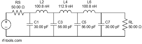
When assessing filter performance for an FM transmitter, given that the frequency reponse drops linearly (except for Cauer filters) as frequency increases, the worst performance will be at harmonics of 87.5 MHz. Whatever is achieved at that frequency will be bettered at harmonics of 108 MHz which is higher in frequency. The filter illustrated above has a largely flat frequency response to around 113 MHz, and then attenuates harmonics as follows.
| Harmonic | Frequencies | Attenuation |
|---|---|---|
| 2nd | 175 MHz 216 MHz | 36 dB 51 dB |
| 3rd | 262.5 MHz 324 MHz | 64 dB 78 dB |
| 4th | 350 MHz 432 MHz | Better than 80 dB |
Note that these ideal, calculated values will be limited by the method of construction. A filter built on printed circuit board (PCB) in limited space will never perform as well as one constructed in a seperate metal can with each inductor isolated from its neighbours. In practice, a compact, PCB based low-pass filter would struggle to achieve much more than around 60 to 70 dB harmonic rejection but for low power transmitters, this should be sufficient (and indeed meets the Ofcom code of practice) which for a 1 Watt transmitter requires that harmonics and spurious should be 46 dB below the carrier. Given that the second harmonic of the raw FM transmitter, even at 175 MHz, is already more than 10 dB below the carrier the additional 36 dB of attenuation provided by the filter will meet the Ofcom requirements with no difficulties.
add comment
( 325 views )
| permalink
| 

 ( 2.6 / 1048 )
( 2.6 / 1048 )