
5G Explained (Part 1): Massive MIMO
Wireless Waffle intends to focus on developments in 5G mobile services amongst our usual flotsam and jetsam of scepticism and general incredulity over wireless matters. But what makes 5G different from 4G, or for that matter 4G from 3G? How are the ever faster connection speeds accomplished, and what are the implications for me and you? Over a series of posts, we intend to explain a little of what is behind these advances in mobile technology, which if nothing else, will serve to show just how sophisticated modern mobile networks are.
In old fashioned radio technologies, the transmitter uses a single antenna to emit a signal, and the receiver uses a single antenna to receive the signal (incidentally known as single input, single output or SISO). This works fine but neglects one of the most common propagation conditions that can upset reception of a radio signal: reflections. The reception of a signal reflected off an object in addition to the direct signal can lead to all manner of problems. One of the most common was, in the days of analogue television, what was known as 'ghosting'.
 Analogue television pictures are drawn line-by-line by a dot that whizzes across the screen from left to right. Any reflection will, by the simple laws of geometry, have travelled further than one directly from the transmitter and thus will take slightly longer to arrive. This produces a second image, that is 'delayed' compared to the direct signal, and this delayed picture would appear to the left of the main signal, as a ghost of the main picture.
In digital television, this problem has been dealt with by slowing down the transmission of the data, such that the typical length of a delay (measured in microseconds) is far less than the length of time used to send each bit, and thus you can effectively ignore the short period of time for which the delayed signal and the direct signal might be different from each other and switch off the receiver for a short while until the situation settles down. The time which the receiver waits for the situation to settle down is known as the guard interval and can be adjusted by the broadcaster to take account of different reflection environments (i.e. in a city where reflections tend to be strong, but over small distances, compared to in a rural area where the reflections might be from buildings or structures several kilometers away).
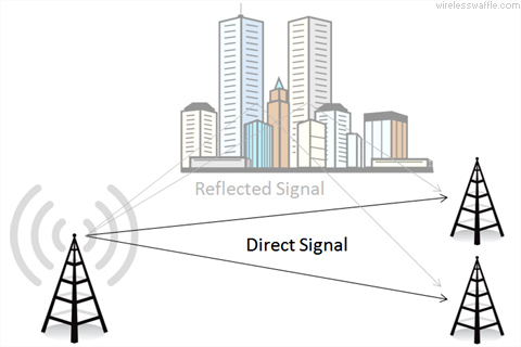
But what if you could be cleverer than just ignoring the reflection, and find a way of using it to benefit reception instead of being a detriment to it? Take the example illustrated above. A single transmitter is being received by two adjacent antennas, but as well as receiving a signal that has travelled directly from the transmitter, they are also receiving a reflection. If the signal being received at each antenna is compared with the other, the direct signal will appear identical, having travelled exactly the same distance. The reflection, however, will be different at each antenna, having travelled marginally different distances.
This fact can be used to do something very clever. If you compare the signals at both antennas, and only seek out the elements that are identical, you can effectively filter out the direct signal and throw away the reflection. However, you can go one step further. If you subtract the signal at one antenna from that of the other, the direct signal will cancel out, and you will be left with only the reflected signal. Thus it is possible to receive both the direct signal and the reflected signal independently from one another.
Now imagine you could tell the transmitter this information (i.e. that you were receiving two copies of the signal it was transmitting, one directly and one via a reflection). Using the same techniques but in reverse, it would be possible for the transmitter to send two independent sets of information, one via the direct path, and one via the reflection. You could use the same frequency twice between the same two points, doubling spectrum efficiency in one swipe. By using more antennas, more reflections can be handled and the same frequency can be re-used multiple times.
Such techniques are not science-fiction. One of the most important developments of recent years is the implementation of what is known as Multiple Input, Multiple Output (MIMO) technology. MIMO uses more than one antenna both at the transmitter and receiver to achieve exactly this outcome. One of the first widespread uses of MIMO was in the IEEE 802.11n standard for WiFi. This can use up to 4 antennas for the transmitter and up to 4 for the receiver. As reflections are common indoors (e.g. from walls, ceilings) this works very well and allows the same frequency to be re-used multiple times to achieve higher data throughput (theoretically up to 600 Mbps). This technique has been built into WiFi hotspots, laptops and mobile phones since the early 2010s and is now defacto in new devices.
 4G (LTE) also uses MIMO techniques to do exactly the same thing. It is becoming increasingly common for at least 4 antennas to be used at the base station and 2 or more in a mobile handset. Where 5G will change this, is that what is being called 'massive MIMO' will be employed. This means that the base station may have up to 256 antennas, and potentially something similar in handsets. This will allow the same frequencies to be reused hundreds of times within a cell, making spectrum efficiency very high, but also massively increasing the capacity of a cell and thus the connection speed experienced by the users.
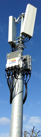
You might think that 256 antennas will weigh down cell towers, but as we are mostly talking about frequencies above 24 GHz, which have a wavelength of 1.2 cm or less, an array of 16 antennas high by 16 across (i.e. 256 in total) need only be 20 cm square. Even at lower frequencies such as 2.6 GHz which has a wavelength of 12 cm, and a panel of 4 antennas wide by 8 high, each antenna having both horizontal and vertical polarisation (making for 64 MIMO antennas) would only measure roughly 50 cm across and 1 m high, which is not that much bigger than traditional panel antennas used today. The picture on the left is of a 2.6 GHz MIMO panel antenna in use at the 5G Innovation Centre in the UK.
Another way to think about massive MIMO is to consider that with 256 antennas, you could use them in the same way as elements of a directional antenna, and form narrow beams pointing at each user. Each user could then use the full amount of spectrum that is available in the cell (or more if there are enough spare antennas to also handle the reflections). This is known as beamforming, and is one of the applications of MIMO.
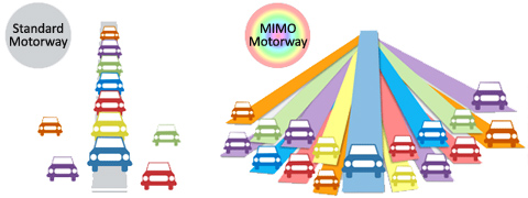
The impact of massive MIMO has been likened to that of using a multi-lane motorway. On a standard motorway, each car shares a few lanes with other drivers and thus is constrained in what it can do by the other cars on the road. On a massive MIMO motorway, each car has its own lane and thus can do what it wishes.
There is one potential concern that MIMO brings. If you imagine all 256 antennas pointing in the same direction, the cumulative amount of radio energy being sent in that direction could be very high and some have expressed fears that this may exceed safety thresholds. The ITU has even held a workshop on the topic. The concerns also centre around the fact that it is foreseen that 5G cell deployments will be on structures such as street and traffic lights which put them much closer to pedestrians and drivers than existing deployments. Nonetheless, massive MIMO is a key part of 5G technology and will bring significant gains in spectrum efficiency.
In old fashioned radio technologies, the transmitter uses a single antenna to emit a signal, and the receiver uses a single antenna to receive the signal (incidentally known as single input, single output or SISO). This works fine but neglects one of the most common propagation conditions that can upset reception of a radio signal: reflections. The reception of a signal reflected off an object in addition to the direct signal can lead to all manner of problems. One of the most common was, in the days of analogue television, what was known as 'ghosting'.
;) Analogue television pictures are drawn line-by-line by a dot that whizzes across the screen from left to right. Any reflection will, by the simple laws of geometry, have travelled further than one directly from the transmitter and thus will take slightly longer to arrive. This produces a second image, that is 'delayed' compared to the direct signal, and this delayed picture would appear to the left of the main signal, as a ghost of the main picture.
Analogue television pictures are drawn line-by-line by a dot that whizzes across the screen from left to right. Any reflection will, by the simple laws of geometry, have travelled further than one directly from the transmitter and thus will take slightly longer to arrive. This produces a second image, that is 'delayed' compared to the direct signal, and this delayed picture would appear to the left of the main signal, as a ghost of the main picture. In digital television, this problem has been dealt with by slowing down the transmission of the data, such that the typical length of a delay (measured in microseconds) is far less than the length of time used to send each bit, and thus you can effectively ignore the short period of time for which the delayed signal and the direct signal might be different from each other and switch off the receiver for a short while until the situation settles down. The time which the receiver waits for the situation to settle down is known as the guard interval and can be adjusted by the broadcaster to take account of different reflection environments (i.e. in a city where reflections tend to be strong, but over small distances, compared to in a rural area where the reflections might be from buildings or structures several kilometers away).
But what if you could be cleverer than just ignoring the reflection, and find a way of using it to benefit reception instead of being a detriment to it? Take the example illustrated above. A single transmitter is being received by two adjacent antennas, but as well as receiving a signal that has travelled directly from the transmitter, they are also receiving a reflection. If the signal being received at each antenna is compared with the other, the direct signal will appear identical, having travelled exactly the same distance. The reflection, however, will be different at each antenna, having travelled marginally different distances.
This fact can be used to do something very clever. If you compare the signals at both antennas, and only seek out the elements that are identical, you can effectively filter out the direct signal and throw away the reflection. However, you can go one step further. If you subtract the signal at one antenna from that of the other, the direct signal will cancel out, and you will be left with only the reflected signal. Thus it is possible to receive both the direct signal and the reflected signal independently from one another.
Now imagine you could tell the transmitter this information (i.e. that you were receiving two copies of the signal it was transmitting, one directly and one via a reflection). Using the same techniques but in reverse, it would be possible for the transmitter to send two independent sets of information, one via the direct path, and one via the reflection. You could use the same frequency twice between the same two points, doubling spectrum efficiency in one swipe. By using more antennas, more reflections can be handled and the same frequency can be re-used multiple times.
Such techniques are not science-fiction. One of the most important developments of recent years is the implementation of what is known as Multiple Input, Multiple Output (MIMO) technology. MIMO uses more than one antenna both at the transmitter and receiver to achieve exactly this outcome. One of the first widespread uses of MIMO was in the IEEE 802.11n standard for WiFi. This can use up to 4 antennas for the transmitter and up to 4 for the receiver. As reflections are common indoors (e.g. from walls, ceilings) this works very well and allows the same frequency to be re-used multiple times to achieve higher data throughput (theoretically up to 600 Mbps). This technique has been built into WiFi hotspots, laptops and mobile phones since the early 2010s and is now defacto in new devices.
4G (LTE) also uses MIMO techniques to do exactly the same thing. It is becoming increasingly common for at least 4 antennas to be used at the base station and 2 or more in a mobile handset. Where 5G will change this, is that what is being called 'massive MIMO' will be employed. This means that the base station may have up to 256 antennas, and potentially something similar in handsets. This will allow the same frequencies to be reused hundreds of times within a cell, making spectrum efficiency very high, but also massively increasing the capacity of a cell and thus the connection speed experienced by the users.You might think that 256 antennas will weigh down cell towers, but as we are mostly talking about frequencies above 24 GHz, which have a wavelength of 1.2 cm or less, an array of 16 antennas high by 16 across (i.e. 256 in total) need only be 20 cm square. Even at lower frequencies such as 2.6 GHz which has a wavelength of 12 cm, and a panel of 4 antennas wide by 8 high, each antenna having both horizontal and vertical polarisation (making for 64 MIMO antennas) would only measure roughly 50 cm across and 1 m high, which is not that much bigger than traditional panel antennas used today. The picture on the left is of a 2.6 GHz MIMO panel antenna in use at the 5G Innovation Centre in the UK.
Another way to think about massive MIMO is to consider that with 256 antennas, you could use them in the same way as elements of a directional antenna, and form narrow beams pointing at each user. Each user could then use the full amount of spectrum that is available in the cell (or more if there are enough spare antennas to also handle the reflections). This is known as beamforming, and is one of the applications of MIMO.
The impact of massive MIMO has been likened to that of using a multi-lane motorway. On a standard motorway, each car shares a few lanes with other drivers and thus is constrained in what it can do by the other cars on the road. On a massive MIMO motorway, each car has its own lane and thus can do what it wishes.
There is one potential concern that MIMO brings. If you imagine all 256 antennas pointing in the same direction, the cumulative amount of radio energy being sent in that direction could be very high and some have expressed fears that this may exceed safety thresholds. The ITU has even held a workshop on the topic. The concerns also centre around the fact that it is foreseen that 5G cell deployments will be on structures such as street and traffic lights which put them much closer to pedestrians and drivers than existing deployments. Nonetheless, massive MIMO is a key part of 5G technology and will bring significant gains in spectrum efficiency.
add comment
( 533 views )
| permalink
| 

 ( 2.8 / 306 )
( 2.8 / 306 )