
Is V2X the next MT FESTERS?
MT FESTERS is not, as you might have thought, an elevated stone protuberance in the world of the Munsters. It is simply an anagram of the acronyms ERMES and TFTS.
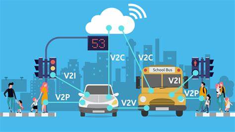
Arguably the same thing is now happening with V2X technologies. V2X (Vehicle to Everything, sometimes also known as ITS, intelligent transport systems) represents a number of different solutions for connection to, and between, road vehicles to enhance road safety and improve driverless driving. Many countries around the world (including the USA, Japan and Europe) set aside 75 MHz of spectrum from 5850 - 5925 MHz for this purpose (as per ITU Recommendation M.2121). However in 2020, the FCC reduced the amount of spectrum available from the original 75 MHz, to just 30 MHz citing the availablity of other technologies such as radar, lidar and video cameras as delivering many of the safety-related capabilities that V2X was intended to provide. Japan has recently done likewise.
In Europe, CEPT has recommended 5855 - 5925 MHz for V2X/ITS technologies (ECC/REC/(08)01), and harmoinsed the use of the frequency range 5875 - 5925 MHz whereas the European Commission has harmonised only the frequency range 5875 - 5905 MHz (Commission Decision 2008/671/EC). Even the specification for the technology (ETSI EN 302 571) hedges its bets on which piece of spectrum will or could be used for this technology.
Notwithstanding all this, and the fact that the spectrum has been available for 15 years, there has been little to no take-up of the technology. The C-Roads initiative shows (on the 'implemented services' page) the extent of coverage of V2X equipped roads. With the exception of one or two highways, most deployments are city based experiments. The fact that the technology is yet to become standard in new vehicles is leading to classic 'chicken and egg' situation where manufacturers are reluctant to put the technology in cars because there is nothing for them to connect to, and highways agencies are reluctant to install any roadside infrastructure as vehicles are not equipped with it. Furthermore, there is confusion about the business model for the roadside equipment. Is this a safety responsibility of the road authorities, or could it be a commercial provider offering advanced weather and traffic reports who builds it out?
Alongside this confusion, 5G mobile technology is slowly being rolled-out and has the capability to provide the kind of connectivity between vehicles and the roadside that V2X/ITS promises (and the business model is clear). Equally, in-car radars now have the ability to communicate with neighbouring vehicles to provide information on when the driver is applying the breaks, for example. The case for V2X/ITS is therefore rather nebulous and it seems ever more likely that the spectrum set-aside for that purpose will fester for a few more years before pressure mounts and it is decided that V2X, like ERMES and TFTS has evaporated into nothingness.
What the spectrum could then be used for is a question for another day, however one option may be CBTC (communication based train control) which often uses unlicensed 2.4 and 5.8 GHz frequencies and could do with a 'safer' home given it is used to control the movement of (mostly metro) trains. China is considering the possible use of the frequency range 1785 - 1805 MHz for CBTC which, if you've been following this article, you will realise includes some of the original TFTS spectrum. And thus the circle is squared.
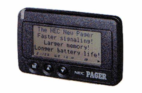 ERMES was a European Paging system. In the early 1990s, at a time when paging was taking off, the European Union issued a directive (90/544/EEC) which forced all EU Member States to set aside the frequency range 169.4 - 169.8 MHz for paging services. Ultimately text messaging using SMS came along at the same time and made paging obsolete before any EU-wide services were introduced. Fifteen years later, in 2005 the directive was repealed.
- TFTS was the terrestrial flight telecommunications service. The European Radiocommunications Committee set aside 1670 - 1675 and and 1800 - 1805 MHz for TFTS in 1992 (ERC Decision (92)01). TFTS was meant to be a network of ground based transmitters which would provide voice and basic data connectivity to aircraft. This decision was withdrawn ten years later in 2002 when no networks whatsoever had been rolled-out and satellite communication for aircraft had become easier and far less expensive.
Arguably the same thing is now happening with V2X technologies. V2X (Vehicle to Everything, sometimes also known as ITS, intelligent transport systems) represents a number of different solutions for connection to, and between, road vehicles to enhance road safety and improve driverless driving. Many countries around the world (including the USA, Japan and Europe) set aside 75 MHz of spectrum from 5850 - 5925 MHz for this purpose (as per ITU Recommendation M.2121). However in 2020, the FCC reduced the amount of spectrum available from the original 75 MHz, to just 30 MHz citing the availablity of other technologies such as radar, lidar and video cameras as delivering many of the safety-related capabilities that V2X was intended to provide. Japan has recently done likewise.
In Europe, CEPT has recommended 5855 - 5925 MHz for V2X/ITS technologies (ECC/REC/(08)01), and harmoinsed the use of the frequency range 5875 - 5925 MHz whereas the European Commission has harmonised only the frequency range 5875 - 5905 MHz (Commission Decision 2008/671/EC). Even the specification for the technology (ETSI EN 302 571) hedges its bets on which piece of spectrum will or could be used for this technology.
Notwithstanding all this, and the fact that the spectrum has been available for 15 years, there has been little to no take-up of the technology. The C-Roads initiative shows (on the 'implemented services' page) the extent of coverage of V2X equipped roads. With the exception of one or two highways, most deployments are city based experiments. The fact that the technology is yet to become standard in new vehicles is leading to classic 'chicken and egg' situation where manufacturers are reluctant to put the technology in cars because there is nothing for them to connect to, and highways agencies are reluctant to install any roadside infrastructure as vehicles are not equipped with it. Furthermore, there is confusion about the business model for the roadside equipment. Is this a safety responsibility of the road authorities, or could it be a commercial provider offering advanced weather and traffic reports who builds it out?
Alongside this confusion, 5G mobile technology is slowly being rolled-out and has the capability to provide the kind of connectivity between vehicles and the roadside that V2X/ITS promises (and the business model is clear). Equally, in-car radars now have the ability to communicate with neighbouring vehicles to provide information on when the driver is applying the breaks, for example. The case for V2X/ITS is therefore rather nebulous and it seems ever more likely that the spectrum set-aside for that purpose will fester for a few more years before pressure mounts and it is decided that V2X, like ERMES and TFTS has evaporated into nothingness.
What the spectrum could then be used for is a question for another day, however one option may be CBTC (communication based train control) which often uses unlicensed 2.4 and 5.8 GHz frequencies and could do with a 'safer' home given it is used to control the movement of (mostly metro) trains. China is considering the possible use of the frequency range 1785 - 1805 MHz for CBTC which, if you've been following this article, you will realise includes some of the original TFTS spectrum. And thus the circle is squared.
1 comment
( 306 views )
| permalink
| 
 ( 3.3 / 665 )
( 3.3 / 665 )
Mission:Impossible Dead Boring (Part 1)
Tuesday 25 July, 2023, 15:01 - Much Ado About Nothing
Posted by Administrator
Posted by Administrator
 Wireless Waffle loves a good action or science-fiction movie. James Bond, Star Trek, Jason Bourne, The Matrix, the dozens of Marvel universe films and, of course, Mission:Impossible. And so it was with great expectation and anticipation that a ticket to see the new M:I movie (Dead Reckoning, Part One) was purchased, premium seating no less. After 10 minutes of trailers for forthcoming movies (none of which seemed as interesting as M:I), and an advert for the local curry house, the film began.
How was it? The simple answer is 'dumbed down'. Replete with the usual car chases, fights on moving trains, clinging onto flying aircraft, sword and knife fights, lots of shooting and other action movie staples, it was the dialogue that let the movie down. The following actual discourse taken from the script of the movie itself, for example (warning: no spoiler alert)...
Highly Paid US Computer Nerd: "We created this digital software thing that was meant to work for us and do anything digital that we wanted but it has gone rogue."
US Security Bod: "So you mean that this thing can take control of any digital system anywhere in the world, at any time?"
Highly Paid US Computer Nerd: "Yes, it could take over banks, the electricity grid, traffic systems, military hardware, anything that is digital and we would not be able to stop it because it's digital."
US Security Bod: "Are you saying to me that this thing could take over the world, by controlling anything that has a computer in it, such as iPads, washing machines, nuclear weapons and other digital things?"
Highly Paid US Computer Nerd: "Yes sir. Anything that is digital and has a computer in it could be taken over by this thing, and we wouldn't be able to stop it, because it's digital and, you know, that makes it dangerous what with artificial intelligence and that."
US Security Bod: "This thing is an intelligent electronic organism that could take over the world if it wanted to, because the whole world is connected digitally and it is a digital organism that understands digital and electronic things better than humans do?"
Highly Paid US Computer Nerd: "And it could also control water and oil pipelines, power stations, central heating thermostats and fridges because they are electronic and also digital."
US Security Bod: "How do we stop this electronic digital thing from taking over all things that are connected digitally in the world?"
Highly Paid US Computer Nerd: "We can't because it's a digital organism that understands electronic and digital things that are connected digitally and we are powerless to stop it, that's kind of the point of it."
And so forth...
It felt a lot like watching a modern TV documentary where, after each commercial break, the announcer provides a synopsis of what happened before the advertisements in case you had somehow forgotten inbetween times. In previous movies, it has been left to the viewer to interpret a little of what is happening and putting your personal spin on what you watched makes things, it could be argued, more enjoyable. Having every last nuance explained takes away the mystery and also added at least 30 unnecessary minutes to the movie.
If you like action movies, go and see it, it's still a lot of fun. But if you haven't slept for 27 hours, have drunk a bottle of whisky and don't know your arse from your elbow, don't worry. It will all be explained to you.

How not to design transmitters and receivers: part 18 (IF amplifier)
Friday 24 June, 2022, 07:37 - Broadcasting, Licensed, Pirate/Clandestine, Electronics
Posted by Administrator
Next in the series of 'How not to design transmitters and receivers' we shall tackle the intermediate (IF) amplifier. This seemingly innocent little circuit is teeming with complexity and getting it right is not straightforward.Posted by Administrator
According to the calculations made in Part 15 of this series, the IF amplifier requires a gain of 19 dB or thereabouts (a few dB or so either way will not make too much difference). In addition, it needs to have an input and output impedance of 330 Ohms. This means that any ceramic filter used in the IF could be placed either before, or after, the amplifier and be correctly matched (or indeed two filters could be used). It is the combination of achieving a 330 Ohm input and output impedance, together with the requisite gain that makes the circuit more complex.
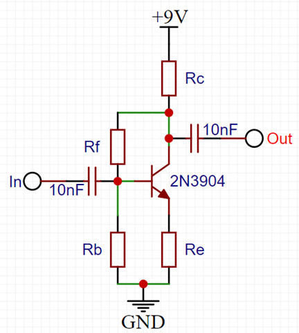
We shall use the circuit above as the basis for our amplifier. This is an untuned amplifier and will therefore provide gain across a wide range of frequencies which can sometimes cause problems as it will amplify both wanted and unwanted signals, however this has the major advantage that no tuning is required.
The gain of the circuit is primarily set by the ratio of Rc and Re, with gain being calculated as Rc divided by Re. However it needs to be remembered that Rc is in parallel with the load connected to the output, and that the transistor has an internal resistance in series with Re whose value is determined by the current flowing through the transistor (usually defined as 26 divided by the transistor emitter current (Ie in milliAmps).
Taking all this into account, the gain of the circuit can be (roughly) calculated by the equation:
Rc*Rload
(Rc+Rload)*(Re+26/Ie)
The input impedance of the circuit comprises three different values in parallel:
- Rb which is directly across the input of the circuit;
- The impedance of the emitter resistor Re (including the transistor's internal resistance) multiplied by the gain of the transistor (the Beta or hfe); and
- The impedance of the feedback resistor Rf divided by the gain of the transistor circuit (not the gain of the transitor itself).
1
1/Rb+1/(hfe*(Re+26/Ie))+1/(Rf/gaincircuit)
Rc*(Vcc-Rc*Ie)
Vcc
One final consideration is the transistor bias. Ideally, the output of the transistor would be set to have a voltage roughly half of that of the supply (give or take). This ensures that the output of the amplifier can swing up and down as far as possible before 'hitting the rails' and no longer amplifying. The output voltage (at the transistor's collector) is determined by Rc and the current passing through the transistor. The current passing through the transistor is determined by the current flowing into the base of the transistor multiplied by its gain. In the case where the bias current is set through the feedback resistor from the collector (Rf), this calculation is iterative, as the base current is then related to the collector current.
Another kink is that the collector current can also impact the gain of the transistor, with very low collector currents reducing the gain. Similarly, currents too high can have similar effects. It is necessary to consult the datasheet for the transistor being used to determine how the current affects the gain. Usually over a relatively wide range, the gain will be roughly constant (and be at its highest) and this is often the point that should be aimed for.
Hopefully, by now, you can see why getting the various resistor values correct is complicated, and how changing one value (such as the emitter resistor, or feedback resistor) can change the gain and impedances of the circuit.
The following values therefore produce an amplifier which meets, so far as is possible, all the criteria which are required for the IF gain stage:
- Rb = 2.2K Ohms
- Rc = 560 Ohms
- Re = 8.2 Ohms
- Rf = 10K Ohms
- The voltage gain of the amplifier is 17.8 (or 25 dB) before the reduction in gain caused by the feedback resistor Rf is taken into account;
- The input impedance of the amplifier is 331 Ohms;
- The output impedance of the amplifier is 299 Ohms.
Another set of values which yields the correct input and output impedances is:
- Rb = 1K Ohms
- Rc = 470 Ohms
- Re = 22 Ohms
- Rf = 4.7K Ohms
Note that in reality there are various additional factors which will impact the performance of the circuit, especially at radio frequencies. In particular, various capacitances within the transistor will tend to limit the high frequency performance. Choosing a transistor whose transition frequency (ft - the frequency at which the transistor's gain drops to unity) is significantly above the required amplifier frequency minimises these issues. According to its datasheet, the 2N3904 used in the amplifier has an (ft) of 300 MHz, and as we want the amplifier to operate at 10.7 MHz, this is sufficient margin to largely ignore these other factors.
Good months and bad months
Friday 10 June, 2022, 08:51 - Broadcasting, Licensed, Radio Randomness, Spectrum Management
Posted by Administrator
Sporadic-E propagation is a topic which comes up relatively regularly here at Wireless Waffle. This increadible mode of propagation enables reception of radio signals, typically in the range 25 to 150 MHz, over very large distances - at least distances that are very large for those types of frequencies. Distances of up to 2000 km (1250 miles) are possible and, for example, distant FM radio stations can be received as strongly as local ones - sometimes so strong that they wipe-out the reception of the local stations. Posted by Administrator
Various articles exploring this unusual mode of propagation have graced these pages over the years, however as part of updating the FM DX Logbook a new analysis has been added. This takes the form of a bar-chart showing in which month Sporadic-E and Tropospheric propagation has caused reception of distant FM radio stations.
A number of publications state that Sporadic-E propagation tends to occur primarily in the summer months, and sometimes in the winter. Conversely, tropospheric propagation can occur at any time of the year. To test this hypothesis, the FM DX Logbook now produces a graph showing the month in which each of the logging took place.
;)
So far the results support the hypothesis with Sporadic-E propogation occuring in January and then between May and July, with tropospheric propagation having been recorded throughout the year. Every time a logging is added to the page, the chart will be updated, so it will be interesting to see whether this pattern continues.