
The Digital Dividend: How does that work then?
Wednesday 20 September, 2006, 12:08 - Licensed
 As anyone who has bought a new television in the UK in the past year or so will know, it is the Government's intention to close down all analogue TV transmitters by the end of the year 2012. It's main reason for doing this is to release some of the channels used for broadcasting so that they can be used for 'new users' (presumably ones that they see as being more lucrative!)
The plan is for a rolling conversion of all television transmitters in the country to change from analogue to digital. In doing this, of the four existing analogue frequencies used to carry BBC1, BBC2, ITV1 and Channel 4, only three of these will continue to be used - one will be freed for the aforementioned mysterious new users. The three frequencies still in use will carry three digital mulitplexes ensuring national provision of all BBC, ITV, Channel 4 services including CBBC, BBC News 24, ITV2, ITV3, E4 and so on, so there's no need to worry about people losing their favourite programmes. At the 80 transmitter sites that already carry digital services of the 4 (or 5) analogue frequencies in use and the 6 digital frequencies in use, only 6 will remain in use, the remainder falling into the pot of those available for other users.
Once the digital switch-over (as it's know) is complete, only UHF channels 21 to 30 and 41 to 62 will still be available for television broadcasting. Channels 31 to 40 and 63 to 68 (and possibly 69) will be freed for new users. The diagram below illustrates this situation. 'S.A.B.' represents services ancilliary to broadcasting (sometimes known as programme making and special events) and includes radiomicrophones, talkback, remote control for cameras, point-to-point audio links - i.e. radio equipment used by people making programmes. Channel 69 is shown hashed as it's not yet clear whether or not it will be given over to new users or remain with S.A.B.
So how can the necessary channels be crammed into two-thirds of the original spectrum? There are now approximately 5,200 individual television transmitters on-air in the UK amounting to around 115 transmitters per available UHF TV channel. After switch-over the number of transmitters will be reduced to around 3,800 - but this has to be squeezed into only 32 channels amounting to around 118 transmitters per channel. So the number of transmitters per channel remains roughly the same, and therefore, in theory, planning the new network should be no more difficult than planning the old one was.
 Let's take a look at a practical example, using the Crystal Palace television transmitter site which serves around 12 million people in and around London. At present channels 23, 26, 30, 33 and 37 are used for analogue transmissions and channels 22, 25, 28, 29, 32 and 34 are used for digital. Of these, channels 32, 33, 34 and 37 will no longer be available for broadcasting after switch-over as they are part of the channels set aside for new users.
 So after switch-over, a combination of the existing analogue and digital channels (i.e. channels 22, 23, 25, 26, 28 and 30) will be used for the purely digital service. Thus the future all-digital transmissions can be squeezed into the remaining broadcasting channels at this particular transmitter site.
 This situation is also fine at the majority of UK transmitter sites including the smaller ones as typically at least 3 of the 4 channels in use at these smaller sites will fall within the untouched broadcast spectrum. Some jiggery-pokery will be necessary at a small number of sites to squash services into the remaining channels but all-in-all the plan works!
The question remains as to what 'new uses' might be made of the freed spectrum. One possiblity is that it might be used for more digital television (maybe mobile TV, portable TV or HD-TV). It might be used for more celluar services (maybe 4G). It might be used for mobile delivery of wireless broadband (maybe using 802.20). Some of it might be needed to house all the displaced S.A.B. users who currently occupy channel 69 (and to a lesser extent also heavily occupy channels 63 to 68). At present it's anyone's guess as to the need for and use of this spectrum but one thing is for certain, the UK Government will be rubbing their hands together in glee at the potential for raising a pot of gold for selling it.
add comment
( 1133 views )
| permalink
| 

 ( 3 / 14503 )
( 3 / 14503 )
All-band Antennas for Skinflints
Thursday 7 September, 2006, 08:44 - Amateur Radio
Posted by Administrator
With apologies to anyone who may be offended: radio amateurs tend to be a tight-fisted bunch. Often this attitude perpetrates from having other priorities in life (family, holidays, beer etc); sometimes it stems from wishing to prove the age-old maxim 'any fool can do for a pound, what a good engineer can do for a penny'; sometimes it is as a result of having grown up scrimping and saving for the latest hi-spec transistor (which are now available for 5 pence from RadioShack); and sometimes, to be fair, it's just because they don't have much money.Posted by Administrator
However, it's equally fair to say that radio amateurs tend to be very ingenious. They have often been at the forefront of the development of new radio technologies, and even today, when technology has massively overtaken the capability of most amateurs, they still find clever solutions to a range of radio problems.
 One problem which amateurs have been finding solutions to for years, is the problem of installing a single aerial which can cover the wide range of frequencies which hams are allocated, specifically the HF (high frequency) bands, sometimes called short-wave (SW). Prior to the World Administrative Radio Conference in 1979 (WARC-79), the amateur HF bands were at frequencies of 1.8, 3.5, 7, 14, 21 and 28 MHz. Having a single antenna which can work on all these bands would be great:
- it would be really cheap compared to lots of individual antennas; and
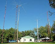
- it would save the back garden from looking like an antenna farm.
Now the scholars amongst you will notice that many of these bands are harmonically related, that is to say that they are multiples of each other: 1.8 times 2 equals 3.6. 7 times 2 equals 14. 7 times 3 equals 21. 14 times 2 equals 28 and so on. Indeed if you start with a frequency of 1.75 MHz (just below 1.8 MHz), there are harmonics at 3.5, 7, 14, 21 and 28 MHz, covering all the bands. Is this fact of any use? Yes it is! An antenna that is 1 wavelength long at 1.75 MHz, will be 2 wavelengths long at 3.5 MHz, 4 wavelengths long at 7 MHz and so on. And, the centre feed point impedance of an antenna that is an exact integer multiple of 1 wavelength is always the same, at around 5000 Ohms. So if we use a broadband transformer capable of converting a 5000 Ohm impedance to that of our transmitter (typically 50 Ohm) a 1 wavelength long antenna at 1.75 MHz will work perfectly well on all these bands. However, It would be 171 metres (or 562 feet) long - not exactly practical (a version with the lowest frequency of 3.5 MHz would still be 86 metres or 281 feet long). Nor is it that easy to produce a broadband transformer that can effect such a drastic change in impedance over such a wide range of frequencies.
 One antenna which aims to address this problem using a little less wire is the G5RV. This is a centre-fed half-wave antenna which, by using an open-wire feeder manages to transform the feed impedance of the antenna on multiple bands to close to the 50 Ohms we require for our transmitter. A G5RV cut for operation on all (pre-WARC 79) bands from 3.5 to 28 MHz is just 31 metres (102 feet) long, a vast improvement in space on our theoretical antenna above.
Another multi-band antenna is the W3DZZ. This 33 metre (108 feet) long antenna uses the fact that a trap represents an inductor below its resonant frequency and a capacitor above it. By carefully choosing the value of the inductor and capacitor in the trap, the antenna can be made to resonate on a number of bands, being an odd multiple of a half wavelength on each (and thus having the same feed impedance).
But: this isn't the end of the problem as, in 1979, along come three new HF amateur bands (10.1, 18.1 and 24.9 MHz)none of which are harmonically related to either 1.8 or 3.5 MHz. Whilst a good antenna tuning unit (ATU) used with a G5RV will allow a reasonable match on these new bands, and the W3DZZ covers 24.9 as well as 3.5, 7, 14, 21 and 28 MHz, the happy situation of being able to use a single antenna on all bands without an ATU was no longer with us. Or was it?
As I said before, radio amateurs are a tight-fisted bunch and not wanting to spend money on multiple antennas, they began to search for an all-band no-tuner antenna. The best attempt at this was the ZS6BKW/G0GSF antenna, which is a modified version of the G5RV. This antenna requires no tuner on the 7, 14, 18.1, 24.9 and 28 MHz bands for an antenna that is just 29 metres (93 feet) long, not bad, but still not quite there.
 We turn our attention then, to the Windom antenna, which works on 3.5, 7, 10, 14, 18.1, 24.9 and 28 MHz (and rumours claim, 50 MHz too) with no tuner (some modifications can also make it work on 21 MHz too). What an astonishing feat of modern computer-aided design?! Nope, the Windom actually dates back to 1929.
Finally, there's the T2FD. This antenna uses a resistor to absorb some of the power when the antenna is not a particularly good match. It has a very wideband performance, however this is at the cost of low gain at some frequencies. Great for receiving, not so good for transmitting.
So there are some all-band, no-tune antennas, in particular a modified Windom. Which is great, because there's no way most radio hams will pay for anything more complex!
2dBi or 2dBd, that is the question
Wednesday 30 August, 2006, 08:06 - Amateur Radio
 Something that I found confusing when first learning about the 'black art' of radio is that there seemed to be some argument about the gain figures quoted for antennas. Take a look at this example: The gain figure quoted for this Comet GP-3 dual-band 144/432 MHz antenna is shown as 4.5 and 7.2 dB respectively for the two bands. But any 11th grade physics student will tell you that dB or 'deciBel' is just a ratio between two numbers. So a figure of 4.5 dB is meaningless unless it is 4.5 dB with respect to some reference or other - and this is where the confusion arises...
To circumvent this confusion, an additional letter or letters is usually added after the dB to indicate what the reference point is. So 'dBuV' is 'dB relative to 1 microVolt (uV)', and 'dBm' is 'dB relative to 1 milliWatt (m)' and 'dBW' is 'dB relative to 1 Watt'. So what is the reference point for our antenna gain, and why is there potential for a mix-up?
Antenna gain can be measured in 2 different ways. In it's purest form, antenna gain calculations are made with reference to an 'isotropic source' - the measure being dBi. This theoretical antenna radiates signals equally in all directions, up and down, left and right, backwards and forwards. However an isotropic source is just that - theoretical - as if one could be constructed, the maths of antenna design tells us that it would have to be infinately small. So there is another reference point, a standard half-wave dipole (as this is the most basic form of antenna) - indicated by dBd. Now dBd is, in my mind, a more sensible measure as a simple dipole has a gain of... 0 dBd. However the same antenna could be said to also have a gain of 2.15 dBi as a dipole is somewhat larger than our theoretical isotropic source and thus radiates better.
All very straightforward you might think, so what's the problem? As long as I know that I need to subtract 2.15 dB to convert from dBi to dBd then everything's hunky dory isn't it?
 Well, no. Click again on the link to the antenna specification. It shows the gain as 4.5 and 7.2 dB... it doesn't say whether this is dBi or dBd so in fact, the antenna could have a gain of only 2.35 and 5.05 dBd, which doesn't sound quite so good. Indeed if we check the manufacturer's web-site we discover that the quoted gain figures are, indeed, in dBi.
The upshot of all this is that when comparing manufacturers' quoted gain figures to decide whether one antenna claims to be better than another, make sure you're not comparing apples and pears by making sure that you convert all the quoted gain figures to be relative to the same reference point. It doesn't matter whether it's dBi (which manufacturers prefer as it gives a bigger number) or dBd (which 'feels' more sensible) but always be careful if the gain figure is just quoted in dB.
Mystery No. 29612 - Solved!
Wednesday 19 July, 2006, 15:56 - Amateur Radio
Tuning around the amateur bands during recent sporadic-E openings, I regularly stumbled across voice traffic in a slavic language on 29612.0 kHz USB (upper side band). The format of the traffic was clearly not amateur, and given this, and the fact that it is right in the middle of the relatively active 10 metre FM section of the band but was not FM made me wonder what it might be. Enjoying a mystery I managed to make a short recording of some of the traffic [304kB windows media file] at around 14:15 GMT on 17 July 2006. Not speaking whatever language it is I posted a message on the Utility DXers Forum message board. What a great set of individuals! Within half a day I'd received a response that the most likely culprit of the signal I heard was the Russian Air Defence (the Protivovozdushnoy Oborony or PVO) who track all aircraft through their airspace giving a continuous read-out (quite literally!) of the sector quadrant and the corresponding coordinates of each aircraft.
It turns out that the PVO also run a morse code based variant of this service which has been given the designator 'M21' by
 Enigma 2000, the group who monitor 'number stations' such as the Lincolshire Poacher. Looking back through their records shows that a station called 'V21' was active on 30220 kHz in the past. I don't know whether V21 is the voice equivalent of M21 or not, but if it is, presumably they have now moved to 29612 kHz for the time being in a random attempt not to be intercepted. Bit of a silly exercise really given where they've plopped themselves. It makes you wonder whether military radio operators have any idea what goes on around them. To change frequency in order to maintain some kind of covertness is vaguely clever, but to have changed into the middle of a fairly active section of an amateur band is just a bit daft.
I also dropped a note to the UK representative of the IARU Region 1 Monitoring Service, who record and monitor all 'intruders' into the amateur bands. Don't know whether this will make their offender list or not, but it's nice to be on the discovery end of something rather than just following the lead of others!