
Sporadic-al-E
Thursday 13 July, 2006, 08:36 - Licensed
Driving along the M4 motorway yesterday evening, I was trying to listen to the news on BBC Radio 4. As usual, the RDS Alternative Frequency (AF) service was doing a good job at re-tuning my radio to a new transmitter once I disappeared out of the coverage of the one I was tuned to. Not long into my journey I noticed that my radio was struggling to find a clear frequency and that even the best it could find was swamped by interference. Having experienced this before, I wondered whether there might be Sporadic-E propagation around. A quick tune to the low end of the FM band confirmed there was.Sporadic-E propagation exists when the sun's radiation ionises layers of gas in the 'E'-layers of the ionosphere. These ionised layers refract radio signals, often up to high VHF frequencies, enabling signals from far afield to be easily received. Usually such ionisation forms in relatively small 'clouds' such that the signals which are refracted in any one area might differ significantly from those received in another. Often from any given point the signals received are from one specific area.
It can be fun tuning around the FM band at times when Sprodic-E is active as stations from typically 1,000 or more miles away can swamp local stations. With the advent of RDS it's also relatively easy to identify the location of the transmitter you are hearing. A good place to listen (in the UK) is the bottom end of the FM band (87.5 - 88.0 MHz) where, unless there is a local RSL station active, there tends to be nothing but static. This is also the frequency range that is first to respond when the Sporadic-E clouds are around. Yesterday, for example, the highest frequency on which I could hear foreign stations was around 90 MHz.
 On my journey yesterday I logged the following stations (the location has been added in after a brief web-search). The map on the right shows the path between me and these stations - you can pretty much see that there must have been 2 'clouds' (one over the Bay of Biscay and the other somewhere near Austria) and how the areas where signals were received from are similar:
87.6 Radio Speranza (Pescara, Italy)
87.7 Antena 1 (Mendro, Portugal)
87.7 HRT HR-1 (Pljesvica, Croatia)
87.8 RNE-3 (Baza, Spain)
87.9 Canal Extremadura (Merida, Spain)
88.0 RNE-5 (probably Huelva, definitely Spain!)
There was also a very strong Spanish station on 88.5 MHz but it never quite registered its RDS and as such remains a mystery! There were also other stations fading in and out, many Spanish, some Italian and Portuguese and a few French, however none were receivable long enough to register their name or RDS.
None of this is particularly amazing.
 Sproadic-E propagation is common, especially during the summer months. However, it is most common at the height of the sun's 11 year solar cycle. At the moment, though, the sun is at the lowest point of its 11 year cycle. And radio amateurs monitoring the 6 metre amateur band have also regularly experienced enhanced propagation over the past 2 months. This shouldn't really occur. It might be that the sun has been a bit more lively than it should have been - I'm useless at interpreting the complex solar data - but those that do can tell me that the recent conditions are not normal. So what is going on? My own theory, for what it's worth, is that propagation conditions are not just a function of the sun's activity but are also connected to weather conditions here on Earth. This year in the UK we've had at least 3 weeks of weather where temperatures were 10C above the seasonal norm. Could global warming also be playing havoc with radio propagation? If anyone has a few hundred thousand pounds to spare, I would be happy to investigate further!
2 comments
( 1958 views )
| permalink
| 
 ( 3.2 / 14520 )
( 3.2 / 14520 )
Wire-More LAN (Part III)
Tuesday 27 June, 2006, 08:13 - Radio Randomness
Looking back at the analysis of WiFi antenna performance I conducted recently, it struck me that to maximise the performance of a Wireless LAN there are two factors at play. One is the strength of the signal, clearly enhanced by the higher gain antenna. The other is the amount of background noise. It is not for nothing that the quality of the link from the wireless access point to the computers is measured in terms of 'signal to noise'. Wireless LANs (at least variants 802.11b and 802.11g) operate in the frequency range 2400 - 2483.5 MHz (this extends to 2495 MHz in Japan only, and not all of the band is available in all countries, noteably France which does not have access to frequencies below 2450 MHz), known as the 2.4 GHz band. This band is not exclusively set aside for use by WiFi equipment, but is in fact shared with many different users. The transmitters of each of these users will increase the overall background noise in the band and if strong enough, will cause direct interference.
The 2.4 GHz band is classified as an 'Industrial, Scientific and Medical' or ISM band, meaning that it can be used by a range of non-communicating radio transmitters such as microwave ovens, industrial paint and biscuit drying machines and medical thermal heating devices. These ISM devices typically use very high powered transmitters (900 Watts plus even for a domestic microwave oven) and thus have the potential to cause enormous amounts of interference in their immediate proximity. However the band is also shared with a number of other users including the military, aeronautical radars, wireless video cameras (both professional and domestic), radio amateurs and a whole plethora of low-powered devices in particular Bluetooth. And, of course, other WiFi systems.
If we want to maximise the range of our Wireless LAN installation, it is therefore important to try and select a frequency (channel) which contains the lowest possible number of other users and thus is likely to have the lowest possible amount of interference or noise present.
Wireless LANs, based on the 802.11b/g standard offer us the option of 13 different channels depending on which country we're in (14 in Japan). However these channels are not independent of each other, they overlap very significantly. The 13 European channels have centre frequencies from 2412 to 2472 MHz inclusive, spaced at 5 MHz intervals. However the bandwidth occupied by a transmitter is 22 MHz. This means that transmissions on channel 1 actually extend from 2401 to 2423 MHz. This overlaps with transmissions on channels 2, 3, 4 and 5, meaning the next 'clear' channel is number 6. Thus if our neighbour is using channel 1, we should only use channels from 6 upwards if we are to avoid direct interference. Likewise channel 6 overlaps with all channels from 2 to 10! Thus if we are to avoid interference we can only really use 3 channels, either 1, 6 and 11, or if we have the option, 1, 7 and 13 which will give a bit more separation and hence lower interference. The diagram below attempts to illustrate the situation.
But is there any reason to select any of these channels over another? Which ones might have the lowest inherent level of interference and noise from the other sources in the band? Well of the other users, Bluetooth uses the whole band, so there's no particularly better place to go to be to be protected from this. The military and radio amateurs typically use frequencies from 2400 to 2450 MHz, affecting channels 1 to 10 inclusive, however activity is rare. Certain short-range applications (in particular equipment for the detection of movement as well as high power 'RFID' tags) use 2445 - 2455 MHz affecting channels 6 to 11 inclusive (though the effect is most profound on channels 7 to 10). Emissions from microwave ovens (and most other ISM equipment) centre around 2450 MHz, and as such would also affect channels 6 to 11. So from this simple analysis, it would seem like channels 12 and 13 are the most likely to be clearest of interference.
However, by far the most likely source of interference is... other Wireless LAN users. So which channels are most commonly used by other WiFi bods? On a recent train journey from Manchester to London, I let my laptop and trusty 'Netstumbler' software scan the band for LANs, to see which channel was most commonly in use. The results are shown below:
The most commonly used channel was 11 - given the earlier analysis about the channels least likely to be interfered with, it is perhaps not surprising that this is the default channel on which most equipment operates when initially purchased. Equally, it seems that most people give no further thought to the channel number and leave it on 11. Channels 1 and 6 were also relatively well used - again not surprising given that 1, 6 and 11 are the most common interference free line-up.
So, after all this, which channel is most likely to present the lowest overall noise and interference? If there are unlikely to be any other WiFi users in the neighbourhood, I'd choose channel 12 or 13. If there is likely to be lots of other WiFi use nearby, channel 1 is the best bet.

Wire-More LAN (Part II)
Tuesday 20 June, 2006, 12:11 - Radio Randomness
Having gone on about how to extend the range of a wireless LAN using a high gain antenna, the need suddenly arose for the range of my own WiFi connection to be extended so I though I would purchase a 9dBi antenna to see what happened. Being a hardcore engineer, I wanted to try and see whether this antenna really delivered the gain over the original 2dBi antenna which it promised.Antennas and laptop in hand, I used a programme called 'Netstumbler' to record the signal to noise of the reception of my WiFi connection over about a 1 hour period, changing between the standard 2dBi and the higher-gain 9dBi antenna about half way through. The first graph (below) shows the received signal strength over the period. The orange line is the rolling average over a 2 minute period. Without any further analysis, it is immediately apparent that the signal strength received when the 9dBi antenna is installed is higher than with the 2dBi antenna, indicating that it did have some gain as promised.
A quick calculation of the average over the 2 periods showed that the average signal to noise with the 2dBi antenna was 28.8dB, whereas the average signal to noise with the 9dBi antenna was 34.6dB, an increase of 5.8dB - not quite the 7dB increase that should in theory materialise, but not bad nonetheless. For the statisticians amongst you, the standard deviation in both cases was remarkably close at 3.96 and 3.92 dB for the 2 and 9 dBi antennas respectively, indicating that the signal was equally stable (despite the obvious variations) in both instances.
A further analysis of the results (above) shows the distribution of signal strengths produced by the 2 antenns. In this case it is easy to see that the signal produced by the 9dBi antenna (in orange) is consistantly and significantly better than that of the 2dBi antenna (in dark blue).
Whilst the experiment was less than scientific, taken at face value, it does suggest that the signal produced by the 9dBi antenna is a worthwhile improvement over the signal produced by the standard 2dBi antenna as supplied with most WiFi routers. The claims of a '3 to 4 times' increase in the range of coverage have not been tested - maybe I'll do that one day soon.
WiMo, WiMo, It's off to work (DX) we go
Wednesday 14 June, 2006, 08:22 - Amateur Radio
For a while now, I've been considering how best to go about installing a decent multi-band HF antenna that would be unobtrusive but still work. I first tried a long inverted-L made of thin wire running down the garden using the house-hold central heating system as an earth (yes, yes, I know this is a no, no, but it's all I could get my hands on in the area available). It wasn't totally invisible but was largely unobtrusive. It resonated at about 2.5 MHz and with a simple ATU I could tune it to get a low SWR on all bands from 160m (the top end only) to 6m. Of course it's difficult to measure the effectiveness of such an antenna but I did manage one or two true 'DX' contacts with Hong Kong (5976 miles), Tokyo (5915 miles) and Sao Paulo (5984 miles) on bands ranging from 17 to 10 metres. The downside to the antenna was that it received rather a lot of background noise, probably because the vertical portion of the 'L' ran close to lots of IT equipment. I also discovered that next door's television was a major source of RF interference on 20 metres too! However, I couldn't help but feel that performance was probably not even as effective as a straightforward dipole. Having measured my loft, I realised that I only had about 9 metres of space to play with - enough for a 17 metre dipole, but not much more. After a bit of digging around I found an antenna made by WiMO of Germany, which used the fact that, below their resonant frequency, tuned 'L-C' traps become inductors and as such have the effect of electrically shortening an antenna. With clever positioning of two sets of traps, they have produced a trapped-dipole that covers 20, 15 and 10 metres in an overall, occupied space of only 8 metres. This sounded like just the thing for my loft so I ordered one. A week later it arrived.
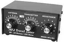
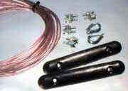 Installation was a cinch, mounting the centre balun transformer from a hook at the apex of the loft, and dangling the two antenna wires over the rafters to sit as close to the roof (and thus as high) as possible. I quickly ran to the shack to see whether or not such an antenna could cope with being in such a confined space (where, I should add, there are electrical cables feeding loft lights as well as a television antenna, splitter and various down-leads and a loft ladder, all of which could de-tune the antenna). A quick tune around and I have to say I was impressed: with no tweaking at all, the antenna provided a perfect 1:1 match at 28.0, 21.05 and 14.15 MHz - a little low in frequency for SSB working - but the match is relatively wide and a little intervention from my MFL-902 'Travel Tuner' ATU quickly solved that problem (oddly, the setting to raise the resonant frequency was the same on all 3 bands...)
How does the antenna perform? At the moment it's difficult to say. I haven't really had enough time to see whether its DX performance can equal my inverted-L, but what I can say is that (a) subjectively, signals on 10, 15 and 20 metres seem a good bit stronger all round than they did before and that (b) my neighbour's television now gives S9 of noise on 20m instead of S7!
 One final note - whilst my ATU will tune the antenna on the 12, 17, 30 and even 40 metre bands, unlike the inverted-L which comprised nothing other than a piece of wire, the WiMo antenna has a 1:1 balun at the centre. This ensures a much better match with the coax feed, and means that the coax down-lead does not radiate. However it does mean that, if the feed-point impedance of the antenna is not near 50 Ohms, there is a potential for much of the power travelling up the feeder to be absorbed by the balun, rather than making it to the antenna. Thus, whilst it might be possible to tune the antenna on these bands, there is a significant danger of burning out the balun - sodon't do it!