
How not to design transmitters and receivers (part 1: voltage controlled oscillators)
Saturday 5 June, 2021, 12:20 - Amateur Radio, Broadcasting, Licensed, Pirate/Clandestine, Electronics, Radio Randomness
Posted by Administrator
Posted by Administrator
 Hasn't lockdown been a bore? There is only so much Netflix or Amazon Prime that it's possible to watch, let alone enjoy. Mind you, having said that, and if you haven't already seen it, Halt And Catch Fire is a must-watch for any kind of nerd or geek who remembers the dodgy, unreliable and overheating computer designs of the early 1980s.
In order to maintain some kind of sanity, in the Wireless Waffle workshop work has been proceeding on the crudely conceived idea of an instrument that will not only supply emissions for use in radio transmissions, but one which would also be capable of receiving them. Or to put it simply, a wideband VHF transmitter and a matching receiver which could be used as an audio link. Having designed and built many of these devices back in the 1990s, it ought to have been relatively straightforward to revisit those designs and modernise them. Alas, RF design is a fickle mistress and in addition to resulting in some truly awful designs, some very nice ones have also emerged. Along the way, many topics have had to be re-learnt all of which makes for some (very techy) content for a series of blog posts which may, in some small way, help those who might seek to replicate this pointless pass-time.
As Julio Iglesias once said, let's Begin (at) The Beg(u)in(e)(ning). There are dozens of designs for simple VHF variable frequency oscillators (VCO) on the internet, so getting something to generate the intial signals ought to be relatively straightforward. However, there is also lots of evidence to suggest that in cases where signals from oscillators are amplified to high power levels, and sent through antennas which are relatively close to the transmitter, radio frequency (RF) feedback can occur causing buzz and hum to the transmitted signal. The way around this is to have the oscillator work on a different frequency to the one being transmitted.
This might seem like an odd thing to do, however it is not uncommon. Two primary methods are used to achieve this:
- A variable oscillator is mixed with a fixed oscillator and the sum (or difference) of the two is then filtered and amplified. For example, a variable oscillator covering 100 to 125 MHz could be mixed with a fixed oscillator at 75 MHz, resulting in outputs either at 175 to 200 MHz (if the two signals are added) or 25 to 50 MHz (if the two are subtracted). The difficulty with this approach is that mixers are, almost by necessity, non-linear devices. In the first case, with the oscillator on 100 MHz, and the wanted output on 175 MHz, the second harmonic of the oscillator would fall at 200 MHz which, being within the 'wanted' output range, could not easily be filtered out. Careful selection of the variable and fixed frequencies can help overcome this, however this limits the possible range of output frequencies and also requires lots of filtering which is fine if the wanted frequency range is relatively narrow, but more difficult if the frequency range is wider.
- The varible oscillator operates at a frequency which is a sub-harmonic of the wanted frequency, and a multiplier is then used to double, triple or multiply the frequency by even higher orders. If we therefore wanted an output from 25 to 50 MHz, we could, for example, use an oscillator running from 8.33 to 16.66 MHz and triple it. Once again, multipliers are also non-linear devices and the 16.66 MHz signal would also be doubled to 33.33 MHz, which being within the wanted output frequency range would also be difficult to filter out. This method therefore is not without its problems and also requires filtering with all the issues associated with that.
Digging around the internet for 'Kalitron' circuits in which the double frequency (or '2f') output is available, yielded very few results. An article entitled, High Frequency VCO Design and Schematics by Iulian Rosu did discuss a Differential Cross-Coupled VCO and though Iulian's design is meant for very high frequencies, his article does provide some useful guidance. One of these is that the transistors should ideally be biased at the point between their saturation and linear regions (i.e. almost fully turned on). It was therefore decided to try and adopt this circuit.
Since getting involved in designing radio equipment in the 90s, the use of PNP transistors for oscillators has always been the preferred Wireless Waffle approach. The primary benefit of this is that the inductor used to set the frequency of the oscillator is grounded, making applying some kind of variable capacitance across it far easier. And so experimentation began. It would have been easy to copy the Veronica approach, however this requires 6 individual coils to be wound, and finding a simpler way to achieve the same results was sought. Getting such an oscillator to work was not difficult, but finding the correct balance of transistor current and bias, and then tapping off the doubled frequency component with sufficient 'oomph' to do something useful with, whilst not disturbing the oscillator's stability proved a complex balancing act. In addition, to keep the costs of the associated (and yet to be designed) phase locked loop (PLL) down by using off-the-shelf high speed CMOS chips also required a method to extract the un-doubled output to be found.
The final design works. Actually, that was meant to be the start of a sentence, but having got as far as 'the final design works', seemed sufficient.
;) An inductor wound on a toroidal core was used for the oscillator, with a secondary winding (not shown in the picture) used to tap off the un-doubled output. This is somewhat fiddly to wind, but with practice becomes much easier and is the alternative to winding the 6 coils used in the Veronica design.
An inductor wound on a toroidal core was used for the oscillator, with a secondary winding (not shown in the picture) used to tap off the un-doubled output. This is somewhat fiddly to wind, but with practice becomes much easier and is the alternative to winding the 6 coils used in the Veronica design.Once oscillating a new issue was identified: the varicap diodes being used to tune the circuit were rectifying the RF generated by the circuit causing mountains of unwanted non-linear signals to be generated. This was partially fixed by not connecting the varicaps directly together but by short-circuiting them at RF with a capacitor whilst driving the DC level through separate resistors. Keeping the drive voltage above around 4 Volts keeps the diodes in their non-rectifying, more linear region though slightly reducing the potential tuning range. Reducing the amplitude of the oscillations would solve this a little but also reduce the potential output power. RF design is nothing if not a set of complicated compromises.
The doubled output from the oscillator is around 10 dBm (10 milliWatts) which is not quite enough to immediately drive a power amplifier to a reasonable level, so a buffer will be needed. The addition of a buffer will add (at a later date) the option to implement an 'out of lock power down' function in which the output of the transmitter is switched off until it has settled on the required frequency, without which a multitude of problems can occur.
The final circuit (or 'schematic' in American English) of the voltage controlled frequency-doubling oscillator (or 'uppy-downy-frequency-makey-matey' in Australian English) is shown below. Layout should be kept as symmetric as possible to minimise the amount of 'f' which is present on the '2f' output. The transistors used were originally type BF451 which are ideal for the task but other PNP RF transistors such as the BF509, BF939 or MPSH81 would work equally well.
;)
Future articles in this series may explore other unbelievably exciting topics such as:
- how not to blow up RF power transistors
- how well soldering irons burn things like skin and phone covers
- why 40 year old transistors trump modern ones
- glaringly obvious mistakes to make when sending PCBs for production
- forgetting that receivers are sensitive devices
- badly matching one stage to another
- getting PLL loop filters to oscillate wildly
- and much, much less...
add comment
( 237 views )
| permalink
| 
 ( 3.1 / 476 )
( 3.1 / 476 )
Suprisingly Strong Tropogation
Friday 8 March, 2019, 13:10 - Broadcasting, Licensed, Radio Randomness, Spectrum Management
Posted by Administrator
A while ago Wireless Waffle added an FM DX logbook listing reception of far distant (a.k.a. DX) FM radio stations which have been received in the UK at various times. Reception of such stations has also been discussed before in particular with reference to sporadic-E propagation. Posted by Administrator
FM stations being received over a long distance by sporadic-E tend to be very strong, and can often overwhealm reception of local stations. Those being received through tropospheric ducting are often somewhat weaker.
| Radio Station | Frequency | Power | Distance | Path Loss | Field Strength |
|---|---|---|---|---|---|
| Kane FM | 103.7 | 25 W | 13 km | 95 dB | 56 dBuV/m |
| France Inter (Lille) | 103.7 | 400 kW | 260 km | 121 dB | 72 dBuV/m |
| France Inter (Caen) | 99.6 | 50 kW | 225 km | 120 dB | 64 dBuV/m |
Assuming free space loss, therefore, the signals from France would be 8 to 16 dB higher than those from the nearby Kane FM transmitter.
However, this is nothing like reality: free space path loss gives a result which would represent the strongest possible signal that could be received. Of course none of the signals would be propagating in this way, as there would be innumerable obstacles along the way that would deviate wildly from 'free space' and the signals would come nowhere near these values, especially those that have travelled 200 km or more from France. Note that various studies have indicated that for reception in a car, a signal strength around 40 dBuV/m is needed suggesting that the additional path loss caused by propagation effects would have been in the order of 16 to 32 dB, which seems reasonable.
FM receivers have an effect called the 'capture ratio'. In general, if two signals are on the same frequency, and one is more than around 3 dB stronger than the other, then the strongest signal will win-out and the weaker one will disappear. So at least it is clear that the signal from France Inter on 103.7 was a few dB stronger from that of Kane FM.
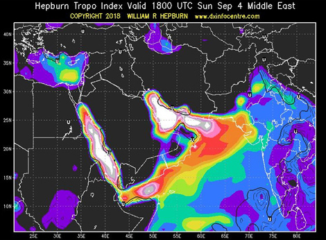
None of this is groundbreaking nor even necessarily that interesting, but it does suggest that the actual path loss obtained during reception by tropospheric ducting can be relatively low. And for radio stations in areas prone to tropospheric ducting (predictions of which can be found on Willam Hepburn's excellent web-site), using a few extra dB of transmitter power may be necessary to ensure reliable reception. Stations, for example, on either side of the Arabian Gulf often use tens of kiloWatts of transmitter power even to provide coverage of just one city, as problems with ducting of signals from the other side of the Gulf are an almost daily occurrence.
Of course, the converse is that using more power then causes increased interference to those on the other end of the duct. Which in turn requires them to turn up their power to combat the problem. Which makes the problem worse. And so forth...
FM DX Logbook
 For many years, Wireless Waffle has enjoyed the occasional bout of FM DXing. That is to say that when the propagation conditions have permitted, time has been enjoyably spent tuning up and down the FM band to see what can be heard.
The logbook of this anomalous reception has been sitting waiting to be published for ages and now, with a quiet weekend with not much else to do has presented itself, it's finally morphed into a web-page of it's own.
Wireless Waffle is therefore proud to announce the FM DX Logbook. If this means nothing to you, then don't take a look. Even if it does, just one look is all it takes, as someone wiser and more lyrical once suggested.

Exponential Data Consumes the Universe
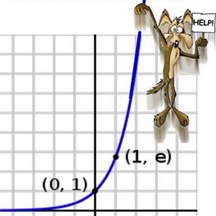
So many organisations and individuals involved in telecommunications continue to use the term 'exponential' to describe the growth in internet traffic, whether carried on fixed networks, or on wireless. Reports such as the ITU.M... forecast continued exponential growth until 2030 and there are numerous publications that cite growth following an exponential curve. But (with the possible expansion of the universe), nothing grows forever, let alone exponentially.
Let's consider the implications of exponential growth in internet data traffic. According to various sources, the amount of data transferred over the internet in 2018 will reach 1 Zettabyte (or 8x10�� bits). If growth continues exponentially at current rates (e.g. around a 50% year-on-year increase), the following things will happen: This is to say nothing of the electrical power requirements. Based on current future expectations of the energy required to transfer a bit of data (around 1 picoJoule per bit), by around 2080 we would need every single Watt of power generated on the planet Earth today to keep the Internet's lights on (let alone the problems of the sizes of batteries that would be needed in mobile devices). By 2113, we would need to capture every milliWatt of power that the Sun emits in order to power the Internet (in essence building a Dyson sphere). Slowly but surely the exponential growth in Internet traffic would begin to consume the whole universe.
It is therefore to be hoped that the universe is actually infinite and continues to expand (though opinions on this are divided), otherwise it will run out of power before our insatiable demand for watching cat videos is finally sated.
 You might wonder what all this has got to do with radio spectrum, as there's always a Wireless Waffle angle on that topic. The simple fact is that although all the energy on the planet may be consumed keeping the Internet going, the amount of radio spectrum required to deliver the speed of connection necessary to transfer that much data will consume all available frequencies far before 2080. This is, of course, the desired goal of the mobile industry!
As Professor Albert Bartlett of the University of Colorado so aptly puts it:
Let's consider the implications of exponential growth in internet data traffic. According to various sources, the amount of data transferred over the internet in 2018 will reach 1 Zettabyte (or 8x10�� bits). If growth continues exponentially at current rates (e.g. around a 50% year-on-year increase), the following things will happen:
 By 2161, the number of bits of data transferred across the internet will equal the number of atoms in a human body.
- By 2229, the number of bits of data transferred across the internet will equal the number of atoms in the planet Earth.
- By 2270, the number of bits of data transferred across the internet will equal the number of atoms in the Solar system.
- By 2329, the number of bits of data transferred across the internet will equal the number of atoms in the Milky Way galaxy (excluding dark matter).
This is to say nothing of the electrical power requirements. Based on current future expectations of the energy required to transfer a bit of data (around 1 picoJoule per bit), by around 2080 we would need every single Watt of power generated on the planet Earth today to keep the Internet's lights on (let alone the problems of the sizes of batteries that would be needed in mobile devices). By 2113, we would need to capture every milliWatt of power that the Sun emits in order to power the Internet (in essence building a Dyson sphere). Slowly but surely the exponential growth in Internet traffic would begin to consume the whole universe. It is therefore to be hoped that the universe is actually infinite and continues to expand (though opinions on this are divided), otherwise it will run out of power before our insatiable demand for watching cat videos is finally sated.
You might wonder what all this has got to do with radio spectrum, as there's always a Wireless Waffle angle on that topic. The simple fact is that although all the energy on the planet may be consumed keeping the Internet going, the amount of radio spectrum required to deliver the speed of connection necessary to transfer that much data will consume all available frequencies far before 2080. This is, of course, the desired goal of the mobile industry!As Professor Albert Bartlett of the University of Colorado so aptly puts it:
The greatest shortcoming of the human race is our inability to understand the exponential function.