
How not to design transmitters and receivers (part 1: voltage controlled oscillators)
Saturday 5 June, 2021, 12:20 - Amateur Radio, Broadcasting, Licensed, Pirate/Clandestine, Electronics, Radio Randomness
Posted by Administrator
Posted by Administrator
 Hasn't lockdown been a bore? There is only so much Netflix or Amazon Prime that it's possible to watch, let alone enjoy. Mind you, having said that, and if you haven't already seen it, Halt And Catch Fire is a must-watch for any kind of nerd or geek who remembers the dodgy, unreliable and overheating computer designs of the early 1980s.
In order to maintain some kind of sanity, in the Wireless Waffle workshop work has been proceeding on the crudely conceived idea of an instrument that will not only supply emissions for use in radio transmissions, but one which would also be capable of receiving them. Or to put it simply, a wideband VHF transmitter and a matching receiver which could be used as an audio link. Having designed and built many of these devices back in the 1990s, it ought to have been relatively straightforward to revisit those designs and modernise them. Alas, RF design is a fickle mistress and in addition to resulting in some truly awful designs, some very nice ones have also emerged. Along the way, many topics have had to be re-learnt all of which makes for some (very techy) content for a series of blog posts which may, in some small way, help those who might seek to replicate this pointless pass-time.
As Julio Iglesias once said, let's Begin (at) The Beg(u)in(e)(ning). There are dozens of designs for simple VHF variable frequency oscillators (VCO) on the internet, so getting something to generate the intial signals ought to be relatively straightforward. However, there is also lots of evidence to suggest that in cases where signals from oscillators are amplified to high power levels, and sent through antennas which are relatively close to the transmitter, radio frequency (RF) feedback can occur causing buzz and hum to the transmitted signal. The way around this is to have the oscillator work on a different frequency to the one being transmitted.
This might seem like an odd thing to do, however it is not uncommon. Two primary methods are used to achieve this:
- A variable oscillator is mixed with a fixed oscillator and the sum (or difference) of the two is then filtered and amplified. For example, a variable oscillator covering 100 to 125 MHz could be mixed with a fixed oscillator at 75 MHz, resulting in outputs either at 175 to 200 MHz (if the two signals are added) or 25 to 50 MHz (if the two are subtracted). The difficulty with this approach is that mixers are, almost by necessity, non-linear devices. In the first case, with the oscillator on 100 MHz, and the wanted output on 175 MHz, the second harmonic of the oscillator would fall at 200 MHz which, being within the 'wanted' output range, could not easily be filtered out. Careful selection of the variable and fixed frequencies can help overcome this, however this limits the possible range of output frequencies and also requires lots of filtering which is fine if the wanted frequency range is relatively narrow, but more difficult if the frequency range is wider.
- The varible oscillator operates at a frequency which is a sub-harmonic of the wanted frequency, and a multiplier is then used to double, triple or multiply the frequency by even higher orders. If we therefore wanted an output from 25 to 50 MHz, we could, for example, use an oscillator running from 8.33 to 16.66 MHz and triple it. Once again, multipliers are also non-linear devices and the 16.66 MHz signal would also be doubled to 33.33 MHz, which being within the wanted output frequency range would also be difficult to filter out. This method therefore is not without its problems and also requires filtering with all the issues associated with that.
Digging around the internet for 'Kalitron' circuits in which the double frequency (or '2f') output is available, yielded very few results. An article entitled, High Frequency VCO Design and Schematics by Iulian Rosu did discuss a Differential Cross-Coupled VCO and though Iulian's design is meant for very high frequencies, his article does provide some useful guidance. One of these is that the transistors should ideally be biased at the point between their saturation and linear regions (i.e. almost fully turned on). It was therefore decided to try and adopt this circuit.
Since getting involved in designing radio equipment in the 90s, the use of PNP transistors for oscillators has always been the preferred Wireless Waffle approach. The primary benefit of this is that the inductor used to set the frequency of the oscillator is grounded, making applying some kind of variable capacitance across it far easier. And so experimentation began. It would have been easy to copy the Veronica approach, however this requires 6 individual coils to be wound, and finding a simpler way to achieve the same results was sought. Getting such an oscillator to work was not difficult, but finding the correct balance of transistor current and bias, and then tapping off the doubled frequency component with sufficient 'oomph' to do something useful with, whilst not disturbing the oscillator's stability proved a complex balancing act. In addition, to keep the costs of the associated (and yet to be designed) phase locked loop (PLL) down by using off-the-shelf high speed CMOS chips also required a method to extract the un-doubled output to be found.
The final design works. Actually, that was meant to be the start of a sentence, but having got as far as 'the final design works', seemed sufficient.
;) An inductor wound on a toroidal core was used for the oscillator, with a secondary winding (not shown in the picture) used to tap off the un-doubled output. This is somewhat fiddly to wind, but with practice becomes much easier and is the alternative to winding the 6 coils used in the Veronica design.
An inductor wound on a toroidal core was used for the oscillator, with a secondary winding (not shown in the picture) used to tap off the un-doubled output. This is somewhat fiddly to wind, but with practice becomes much easier and is the alternative to winding the 6 coils used in the Veronica design.Once oscillating a new issue was identified: the varicap diodes being used to tune the circuit were rectifying the RF generated by the circuit causing mountains of unwanted non-linear signals to be generated. This was partially fixed by not connecting the varicaps directly together but by short-circuiting them at RF with a capacitor whilst driving the DC level through separate resistors. Keeping the drive voltage above around 4 Volts keeps the diodes in their non-rectifying, more linear region though slightly reducing the potential tuning range. Reducing the amplitude of the oscillations would solve this a little but also reduce the potential output power. RF design is nothing if not a set of complicated compromises.
The doubled output from the oscillator is around 10 dBm (10 milliWatts) which is not quite enough to immediately drive a power amplifier to a reasonable level, so a buffer will be needed. The addition of a buffer will add (at a later date) the option to implement an 'out of lock power down' function in which the output of the transmitter is switched off until it has settled on the required frequency, without which a multitude of problems can occur.
The final circuit (or 'schematic' in American English) of the voltage controlled frequency-doubling oscillator (or 'uppy-downy-frequency-makey-matey' in Australian English) is shown below. Layout should be kept as symmetric as possible to minimise the amount of 'f' which is present on the '2f' output. The transistors used were originally type BF451 which are ideal for the task but other PNP RF transistors such as the BF509, BF939 or MPSH81 would work equally well.
;)
Future articles in this series may explore other unbelievably exciting topics such as:
- how not to blow up RF power transistors
- how well soldering irons burn things like skin and phone covers
- why 40 year old transistors trump modern ones
- glaringly obvious mistakes to make when sending PCBs for production
- forgetting that receivers are sensitive devices
- badly matching one stage to another
- getting PLL loop filters to oscillate wildly
- and much, much less...
add comment
( 237 views )
| permalink
| 
 ( 3.1 / 476 )
( 3.1 / 476 )
Resistor Colour Codes
Monday 1 February, 2021, 19:54 - Much Ado About Nothing
Posted by Administrator
It's been a while since anything new was added to Wireless Waffle which is for no other reason than a shift in focus to things more practical. During the Covid lock-ups time has been spent re-igniting an age-old passion for electronic construction projects.Posted by Administrator
As part of those projects, it became necessary to be reminded of how the resistor colour code scheme worked, especially for those odd 1% tolerance resistors and their extra bar of complexity. To assist, the Wireless Waffle Resistor Colour Code Calculator or WiWaReCoCo for short, has been developed.
Just click on the link above (or in the links box alongside) and be taken to a mysterious world in which things such as '3.3K' or '4M7' are miraculously translated into different colours. While away those long winter hours seeing if you can work out what to enter to get a fully banana coloured resistor (hint, '4' is yellow), or how to get the stripes of your favourite football team (try 969M for starters).
Fun has never been so mundane!

Four Three Seven
There are currently over 100 satellites which transmit (either as their downlink, or as a beacon) in the 70 cm amateur band. The frequency range 432 - 438 MHz is internationally allocated to the Earth Exploration Satellite Service on a secondary basis, however most of the satellites generally use the amateur satellite allocation of 435 - 438 MHz.
Permission to use the amateur frequencies is given by footnote 5.282 of the frequency allocation table in the ITU Radio Regulations, which states:
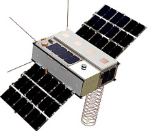 Wireless Waffle wanted to know if there was a particular hotspot within this frequency range where the majority of satellties were clustered, which would make it easier to set up a software radio (SDR) to search for these fleeting signals.
A bit of digging revealed a file containing all of the frequencies used by these satellites and some deft work with Excel formulas then revealed the answer to the question. And the answer is that the majority use frequencies between 437.2 and 437.6 MHz. Of the 176 active satellites frequencies analysed, 100 (or 57%) use frequencies in this range. So now you know and can sleep more soundly in your bed!
Permission to use the amateur frequencies is given by footnote 5.282 of the frequency allocation table in the ITU Radio Regulations, which states:
In the bands 435-438 MHz, 1 260-1 270 MHz, 2 400-2 450 MHz, 3 400-3 410 MHz (in Regions 2 and 3 only) and 5 650-5 670 MHz, the amateur-satellite service may operate subject to not causing harmful interference to other
services operating in accordance with the Table...
Wireless Waffle wanted to know if there was a particular hotspot within this frequency range where the majority of satellties were clustered, which would make it easier to set up a software radio (SDR) to search for these fleeting signals.A bit of digging revealed a file containing all of the frequencies used by these satellites and some deft work with Excel formulas then revealed the answer to the question. And the answer is that the majority use frequencies between 437.2 and 437.6 MHz. Of the 176 active satellites frequencies analysed, 100 (or 57%) use frequencies in this range. So now you know and can sleep more soundly in your bed!
ZX Spectrum Font Frenzy
Wednesday 1 April, 2020, 12:58 - Much Ado About Nothing
Posted by Administrator
An ultra-geeky and totally un-wireless-related post today...Posted by Administrator
You may be aware that as well as running the Wireless Waffle web-site, we also run the Short-Wave.Info web-site. Amazingly, the short-wave site has now had over 27 million visitors. The software is updated from time-to-time to improve the performance or, in the most recent update, to make the map look nicer!
As a result of updating the map software routine, the question of the font used to print the details along the bottom of the image raised itself. For a while this had used a font called 'DejaVu Sans'. However, it seemed more fun if the font could be more interesting and the question arose as to whether it might be possible to use the font that was originally deployed in the ZX Spectrum.
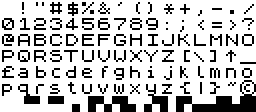 The original ZX Spectrum font uses 8 by 8 pixel blocks (as shown on the right) and isn't that pretty by today's standards, most likely as it is monospace, and as for the majority of characters (apart from the copyright sign) the grid of pixels actually used is only 6 wide by 6 high. This leaves a lot of whitespace around the pixels.
The Short-Wave.Info web-site is written in php, in which there is a function called 'imagestring'. This writes a string of text onto an image and as well as using internal fonts, can also use 'GD' fonts. If the ZX Spectrum character set existed as a GD font file, it would be possible to write text using it and this function.
After some time conducting a web-search, no evidence of a GD version of the Spectrum fonts appeared and so we created one of our own! The image below is now how the bottom of the maps on the Short-Wave.Info web-site looks.

Look at the shiny ZX Spectrum font letters! If you are equally geeky, and also increasingly driven to doing mad things by the current global pandemic lockdown, Wireless Waffle is happy to make the font available for anyone who wants it. Simply download the ZX Spectrum GD font and using 'imageloadfont' you are on your way.
Join us next time on Wireless Waffle, when we share some equally lockdown crazy ideas such as:
- how to make wholesome lard-free bread using old £20 notes and a nail file,
- simulating a Spanish beach holiday with a wet towel and some curdled milk, and
- exciting methods for igniting 5G base stations that are emitting coronavirus.