Thursday 9 December, 2021, 15:57 - Amateur Radio, Broadcasting, Licensed, Pirate/Clandestine, Electronics
In the grand tradition of Wireless Waffle, instead of starting at the beginning of the receiver design, we shall tackle the end, the de-modulator, first. There are a number of ICs that will de-modulate wideband FM signals including modern chips which can act as a complete receiver chain. Notwithstanding these, however, the age old (actually 40 year old) CA3089 and CA3189 (a.k.a. HA1137) are capable IC's which have both technical and economic advantages:
- They are easy to work with, requiring few external parts.
- They can be modified to work with different channel bandwidths and deviations.
- They yield very decent audio signal to noise ratios for strong signals (in excess of 70 dB).
- They have decent AM rejection (i.e. the ability to ignore signal fluctuations).
- They have relatively low audio distortion (around 0.5% THD in a standard configuration).
- They are easy to get hold of.
- They are cheap.
Intermediate frequency (IF) filters typically used in wideband FM receivers are usually based on ceramic filters which almost always have an impedance around 330 Ohms. This means that the input impedance of the de-modulator must be 330 Ohms to match the filter properly and ensure that the performance and frequency response of the filter are correctly achieved. The input impedance of the CA3089/3189 itself is not specified in the datasheet but is generally regarded as being 'high' (i.e. a few kilo Ohms). As such, to match the 330 Ohm impedance of the filter it is simply a matter of placing a 330 Ohm resistor across the input of the chip, as the effect of the parallel input impedance of the chip would be negilgable.
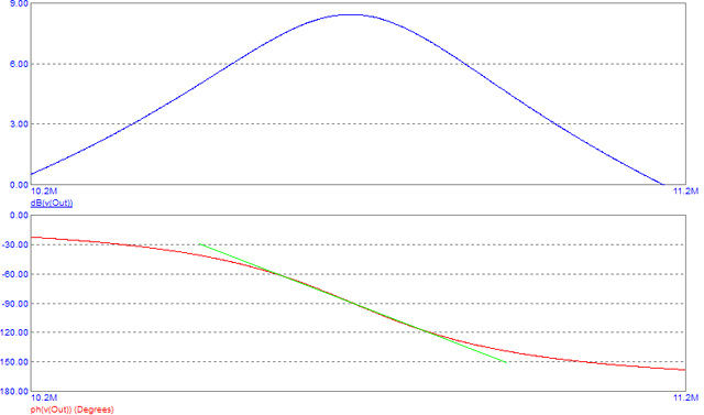
The only other design decision is what channel bandwidth and deviation are to be used. For an 'off-the-shelf' wideband FM transmission, the occupied bandwidth is a smidge over 250 kHz and the deviation is 75 kHz, so this is what the circuit will be designed for. The way in which the IC demodulates the FM signal is to apply the incoming signal to a tuned-circuit via a relatively high impedance inductor. The overall frequency and phase reponse of the circuit is shown in the figure below with frequency response in blue, and phase response in red.

As can be seen, there is a rapid change of phase as the frequency sweeps past 10.7 MHz, and it is this change which the IC uses to demodulate the audio of the FM transmission. The more linear the phase response, the less distorted the recovered modulation is. Ideally the phase change should be a straight line (a straight green line has been drawn on the graph for comparison). For low distortion demodulation of an FM signal at 10.7 MHz, the phase change line should be as flat as possible between approximately 10.575 and 10.825 MHz.
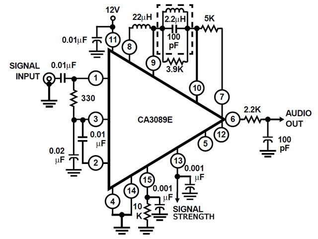
Changing the required bandwidth or deviation response of the receiver entails modifying these 'phase discriminator' components to alter their phase response. The circuit of a simple CA3089/3189 based FM demodulator is shown below. Note that there are a couple of small component differences between the CA3089 and CA3189 circuits.

Some of the pins are shown as being not connected. These relate to a 'mute' circuit which switches off the audio output of the device if there is no incoming signal (often called 'squelch'). This is very useful if being used for a hi-fi receiver as it means that when tuned to the emptiness between stations on the FM dial, the receiver goes quiet rather than emitting a loud hissing noise. It does, however, make it more difficult to eke out weak signals as if they are too weak, they will be muted and therefore they have been left unconnected.
